Build guide
A runway comprises four identical modules, each consisting of a flexible-circuit sensor array, a piezoresistive film and a readout board. The remaining components are a transparent enclosure, a waterproof cover, an overhead camera and a host computer.
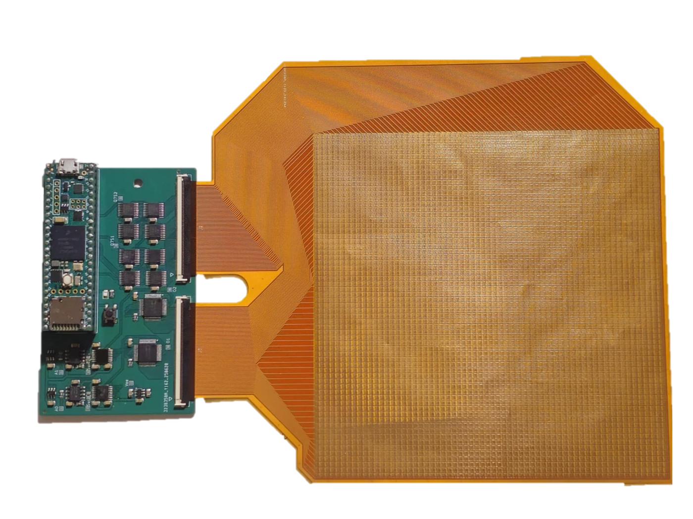
Components
| Component | Per runway | Notes |
|---|---|---|
| Sensor module (flexible PCB, 2 layers, 157.9 × 179.7 mm outline) | 4 | 64 × 64 electrode pairs at 2-mm pitch; no components. Two 70-contact tails connect directly to the readout board. Fabricated as a flexible PCB (FPC) with stiffeners on the tails. |
| Readout board (4-layer PCB, 92 × 56 mm) | 4 | Teensy 4.1, 2 × ADG732 32:1 multiplexers, 2 × AD7476 12-bit ADCs, 8 × 74LVC595 shift registers, 2 × MCP41HV51 digital potentiometers, operational amplifiers and two 70-pin flexible-circuit connectors (Molex 505110). |
| Piezoresistive film (Velostat/Linqstat) | 4 sheets of approximately 140 × 140 mm | Placed over the electrode arrays. |
| Waterproof cloth | approximately 1 m | Forms the walking surface over the sensing area. |
| Acrylic walls and base, USB cables and hub, overhead and side cameras, host computer | The recording software runs on macOS with two 1920 × 1080 cameras; the side view assists manual paw labelling. |
Cost
The parts for one four-module runway cost approximately US$550 (range approximately US$500–750), or approximately US$140 per 64 × 64 module, assuming in-house soldering, bare PCBs from any fabrication service and parts at retail prices (October 2026).
| Per runway | |
|---|---|
| Readout electronics (parts for 4 boards) | $323 |
| 4 × Teensy 4.1 | $126 |
| Readout PCBs and stencil (one order of 5) | ~$13 |
| Flex sensor PCBs (one order of 5) | ~$75 (estimate; $30–200 depending on fab) |
| Piezoresistive film and waterproof cloth | ~$15 |
| Total | ~$550 |
The analog multiplexers and analog-to-digital converters (two of each per board) account for almost half of the total. Digital potentiometers are priced at US$2.00 each (DigiKey, October 2026); other distributors list them at up to approximately US$7, which adds approximately US$40. The flexible sensor PCB should be quoted with the chosen fabrication service. Shipping, taxes, tools, enclosure, cameras and the host computer are not included; optional board-house assembly adds approximately US$155.
Design files
The KiCad sources, the fabrication files used to manufacture the boards and the bill of materials of the readout
board are provided in hardware/ under
the CERN Open Hardware Licence v2 (permissive).
| Board | Files | Fabrication |
|---|---|---|
| Sensor module | KiCad layout and Gerber files | 2-layer flexible PCB, 157.9 × 179.7 mm, with stiffeners under the two tails |
| Readout board | KiCad schematic, layout and Gerber files; bill of materials | 4-layer PCB, 1.6 mm, 91.9 × 56.3 mm |
Fabrication and soldering notes are given in the hardware README.
All readout-board parts except the Teensy 4.1 can be placed by the board house; the JLCPCB BOM and placement files
are in hardware/readout_64x64/jlcpcb/. The Teensy 4.1 is soldered by hand. Parts that are out of stock at
JLCPCB when ordering can be sourced through its parts pre-order or global sourcing services, or soldered by hand.
Assembly
- Readout boards. Solder the components, mounting the Teensy 4.1 on pin headers, and install the firmware (below) with a distinct board identifier on each board.
- Sensor connection. Insert the two flexible tails of each sensor module into the connectors of its readout board.
- Array alignment. Place the four sensor modules edge to edge with their taxel grids aligned. The analysis pipeline assumes boards 4, 3, 2 and 1 from left to right along the runway.
- Piezoresistive film. Cover the electrode arrays with the piezoresistive film.
- Enclosure. Lay the waterproof cloth flat over the film, position the walls around the sensing area and mount the overhead camera so that the full floor is in view.
- Verification. Connect the four boards to the host computer, run
live_view_runway.pyand confirm that the indicator LED of every board is lit and that applied pressure appears at the corresponding location.
Steps 2–4 and 6 are shown in Supplementary Video 1 (93 s).
Firmware
The firmware is provided in acquisition/firmware/
and is installed with the Arduino IDE, Teensyduino and the MCP41HVX1 digital-potentiometer library.
- Set
BOARD_ID(line 5) to 1, 2, 3 or 4 before programming each board. The identifier is transmitted in every packet. - On power-up, each board awaits a configuration line (
M threshold digipot) from the host, sets its gain, acknowledges withOKand begins streaming. It executes the adaptive sampling loop; each frame consists of a header (0xDEADBEEF, board identifier, number of measurements, frame counter) followed by (index, value) pairs.
Recording
acquisition/record_runway.py configures the four boards, starts them and the cameras from a common start signal,
and saves runway_tactile_data_<time>_M<M>_T<threshold>_D<digipot>.mat together with one MP4 file per camera with
per-frame timestamps. Serial ports and camera indices are set at the end of the script. The study recordings used a
duration of 90 s, M = 200, threshold 700 and digital-potentiometer setting 100, with cameras at
1920 × 1080 (target 30 frames/s; approximately 25–27 frames/s achieved, so per-frame
timestamps are used for synchronization).
pip install pyserial scipy numpy opencv-python
python acquisition/live_view_runway.py     # live pressure map (no recording)
python acquisition/record_runway.py        # synchronized recording
Calibration
Calibration curves for the four boards used in the study are provided in
data/calibration_0_450/.
Each new set of sensor modules requires its own calibration: each module is loaded through the same cover on a
reference force plate (in the study, three 5-kg load cells with an NAU7802 24-bit amplifier on a Teensy), and the
summed taxel response is fitted to the reference load as described in the README of that folder.